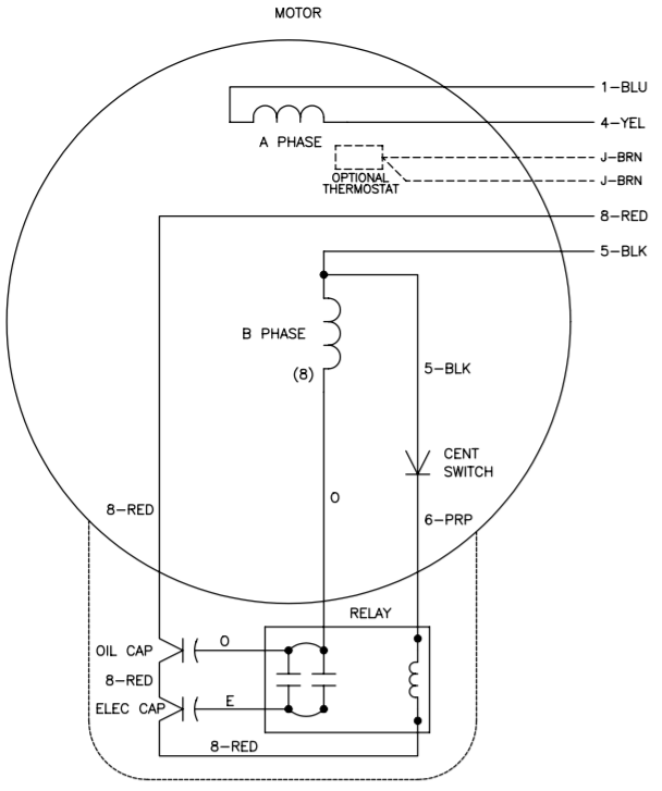
120/240 Motor Wiring Diagrams are important tools for any electrician or home DIY enthusiast. Understanding how motors work, and the wiring diagrams that go along with them, can mean the difference between a successful repair job and a costly one. This article will provide some insight into what you need to know about 120/240 motor wiring diagrams.
When it comes to wiring any motor, it’s important to understand the purpose of the wiring diagram. These diagrams are used to show how the motor is wired, and they provide an easy-to-follow layout of the components needed to wire the motor. Most wiring diagrams will have a diagram of the motor itself, as well as a diagram of the power supply and other components.
The most common type of 120/240 motor wiring diagram is the “split-phase” diagram. This diagram shows two separate circuits, each providing power to the motor. The first circuit provides the voltage for the starting winding of the motor and the second circuit provides the voltage for the running winding of the motor. This type of wiring diagram is typically used for single-phase motors.
For three-phase motors, there are a variety of wiring diagrams available. Some of these diagrams show a basic three-phase system, while others provide more detailed information, such as connections between the motor, power supply, and other components. No matter which type of diagram you use, it’s important to make sure all connections are properly labeled and secured to prevent dangerous electrical shorts.
By understanding the basics of 120/240 motor wiring diagrams, you can ensure your repairs are done safely and correctly. Knowing which diagrams are best suited for your particular motor can help you save time and money in the long run. Be sure to consult a qualified electrician if you have any questions or concerns when wiring your motor.

Magnetic Starter Wiring An Allen Bradley 709 3 Phase For Single 220v The Hobby Machinist

Icm2805 Wiring Diagram Manualzz

Electric Motor Diagrams

Emerson Electric Motor Wiring Help Doityourself Com Community Forums

Show Tell Ac Induction Motors
Electrical Tech Note 103
Electrical Tech Note 103

South Bend Lathes First Of A Few Question New Sb 9 Owner Wiring Questions Practical Machinist Largest Manufacturing Technology Forum On The Web
Ot 110vac 3 Phase Text Plcs Net Interactive Q A

Vfds For Single Phase Applications Keb

Steve Diy Home Improvement Forum

Small Sel Generators Wiring Diagrams

Picture10
.jpg?strip=all)
Wiring Installation

3 Ways To Troubleshoot Ac Motors With A Circuit Tester

Electricity 101 Basic Fundamentals Controls

Split Phase Motors For Medium Duty Applications

Vfd Wiring Diagram Showing Power In Out And Control Device Scientific

How To Install And Wire A Well Pump Installation Guide
