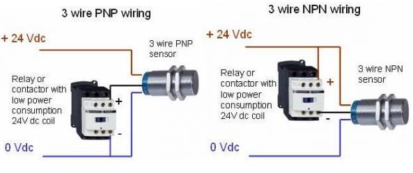
The 3 Wire Proximity Sensor Wiring Diagram is an invaluable tool for any engineer or technician who works with machinery and electrical systems. Whether you’re a professional in the field or a hobbyist who likes to tinker around with electronics, having a good understanding of how proximity sensors work can make all the difference when it comes to diagnosing and repairing problems.
Proximity sensors are used to detect objects or people in the vicinity of a machine or mechanical system. They are used in a variety of industrial and consumer applications, from door openers to automated assembly lines. By following a 3 Wire Proximity Sensor Wiring Diagram, you can easily install and maintain these essential components.
A 3 Wire Proximity Sensor Wiring Diagram is relatively simple to read and understand. The diagram typically includes information about the type of sensor being used, the power source, and the wiring connections. It also shows the output signal generated by the sensor, which can be either a voltage or current. Additionally, the diagram may contain instructions on how to connect the sensor to the power source. This allows you to quickly and easily troubleshoot any issues that may arise during installation or operation.
When working with a 3 Wire Proximity Sensor Wiring Diagram, it’s important to check all the connections before powering up the system. This will ensure that all the components are properly connected and functioning correctly. Additionally, some diagrams may include maintenance tips and advice on how to keep the system running optimally. Following these guidelines will help you get the most out of your proximity sensor system.
In conclusion, the 3 Wire Proximity Sensor Wiring Diagram is an invaluable tool for any engineer or technician who works with machinery and electrical systems. By understanding the diagram, you can quickly install and maintain proximity sensors for any application. Additionally, following the diagram can help you troubleshoot any issues that may arise during installation or operation.

Sensing Fundamentals Back To The Basics Npn Vs Pnp Automation Insights
Proximity Sensors For Rpm Industruino

Mouting Of Inductive Sensors Baumer Usa

Npn And Pnp Proximity Sensors Omch

Capacity Proximity Sensor Cm18 Inductive Photoelectric Solid State Relay Pcb Timer

Ring Inductive Proximity Sensor Switch Abs Npn Pnp No Nc Sn 0 12mm Ip67

3 Wire Inductive Proximity Sensor How To Read The Datasheet Realpars

Panasonic

Npn And Pnp Proximity Sensors Omch

Wiring A Metal Detector With Npn Proximity Sensor On Arduino 14core Com

Back To The Basics How Do I Wire A Dc 2 Sensor Automation Insights

3 Wire Inductive Proximity Sensor How To Read The Datasheet Realpars

Proximity Sensor Inductive M18 3 Wire 120v Ato Com
Realpars How To Wire Discrete Dc Sensors Plc Part 2 Facebook By In This You Will Learn A 3 Sensor

Back To The Basics How Do I Wire My 3 Sensors Automation Insights

Fkc Series Capacitive Proximity Switches Sensors Fiber Optical Sensor
What Is The Difference Between Pnp And Npn When Describing 3 Wire Connection Of A Sensor Schneider Electric Canada

How To Connect Npn Pnp Proximity Sensor Plc Ato Com

Safety Precautions Of Proximity Sensors Cautions For Omron Automation

Clear Instructions On Setting Up Proximity Sensor Duet Forum


