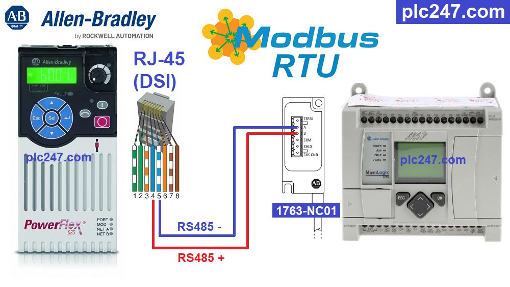
Allen Bradley MicroLogix 1400 Wiring Diagrams are essential for any electrical professional to understand. For many years, electrical professionals have relied on the diagrams included in their products to ensure that they can safely and accurately complete their work. The Allen Bradley MicroLogix 1400 is a programmable logic controller (PLC) that offers a wide range of features and benefits. It is used in many industrial and commercial applications, but understanding how to wire it correctly and safely is vital.
By taking the time to look at an Allen Bradley MicroLogix 1400 wiring diagram, an electrician can quickly and easily gain an understanding of how to connect and control the device. The diagrams provide a detailed overview of the wiring that must be done and the connections that need to be made. Each diagram is designed to show all of the components and connections, including the power supply and the load, along with the correct wiring setup. With this information, an electrician can quickly and easily complete their installation and troubleshooting.
The Allen Bradley MicroLogix 1400 wiring diagram also provides detailed information about any specific components that may be needed for the installation. This includes any special switches, relays, or other components that may be necessary. By knowing exactly what is needed and how to install it, an electrician can save time and money in their work. Additionally, the diagrams can help electricians troubleshoot any problems they encounter during the installation process.
Overall, Allen Bradley MicroLogix 1400 wiring diagrams are an invaluable tool for any electrical professional. The information that is contained within them is essential for ensuring a safe and efficient installation of the PLC. The diagrams provide a detailed overview of the wiring that must be done and the connections that need to be made, as well as any special components that may be required. By taking the time to look at an Allen Bradley MicroLogix 1400 wiring diagram, an electrician can quickly and easily gain a better understanding of how to connect and control the device.

Micrologix 1400 Programmable Controllers Pdf Free

Micrologix 1100 Modbus Rtu Delta Ms300 Tutorial Plc247 Com
Automatic Control Model Of Water Filling System With Allen Bradley Micrologix 1400 Plc

Micrologix 1500 Programmable Logic Controller Systems Allen Bradley
Micrologix Programmable Controllers Selection Guide

Equustek S Dl3500 Df1 Dh A Direct Replacement For Allen Bradley 1770 Kf2 Or 1785 Ke To Data Highway Plus Interface Offers Connectivity From Ethernet Ip Modbus

Micrologix 1200 Power Up Plcs Net Interactive Q A

Rockwell Automation 1766 L32awa Installation Instructions Manual Pdf Manualslib
Application Note 1183 Rockwell Automation Cabling Addendum

Surplus Mac Process Pneumatic Conveying Control Allen Bradley Micrologix 1400 Cooper Industries Llc

Ab Micrologix 1100 Westermo Gdw 11 Plcs Net Interactive Q A

Electrical Solutions Corp Plc Programming

Wiring Diagrams Terminal Block Layouts Allen Bradley Micrologix 1200 User Manual Page 43 Manualslib

Pdf Automatic Control Model Of Water Filling System With Allen Bradley Micrologix 1400 Plc
Teaching Color Sensing Connected Components Building Block
Allen Bradley Automation Course Plc Scada And Vfd Code

Micrologix 1100 Modbus Rtu Powerflex 525 Tutorial Plc247 Com
