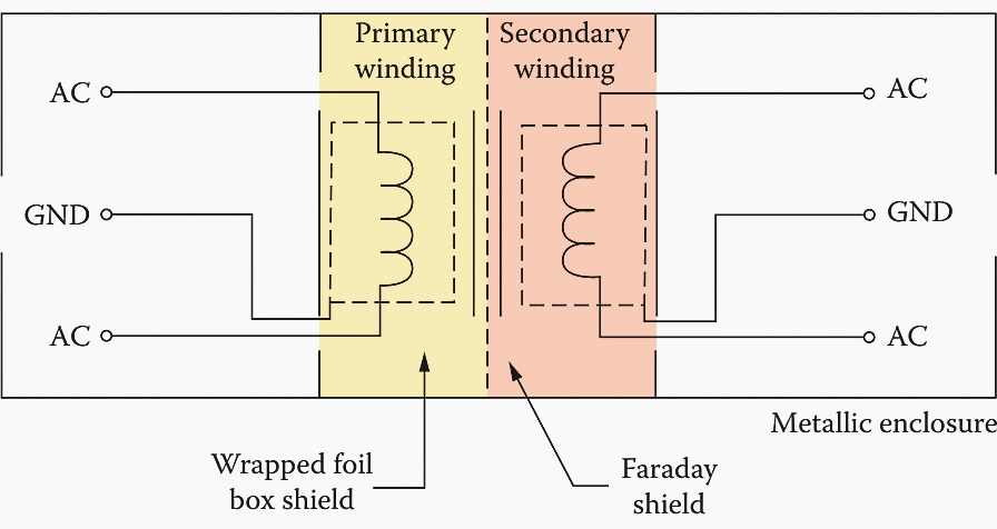
Isolation transformer wiring diagrams are essential when it comes to understanding how an electrical system works. They provide a clear visual representation of the components and wiring that make up a system, and they can help you diagnose problems quickly and accurately. In this article, we’ll discuss what isolation transformers are and why they’re important, as well as the basics of constructing and reading a wiring diagram.
An isolation transformer is a device used to prevent electrical shock by isolating an electrical circuit from the power source. This is done by using two separate windings in the transformer, one connected to the power source and one connected to the circuit. The two windings are magnetically coupled, but electrically isolated, so that any current flowing through the circuit won’t cause a shock. Isolation transformers are often used in medical equipment and other electronics, where safety is a top priority.
When it comes to wiring diagrams, each component of the electrical circuit is represented as a symbol. These symbols show the connections between different parts of the circuit and the sources of power. By looking at the diagram, you can quickly identify which components are connected to which, as well as where the power is coming from and how the circuits are linked. This makes it easier to troubleshoot problems, as well as to plan out new systems.
It’s important to be familiar with isolation transformer wiring diagrams if you’re working with an electrical system. With a good understanding of the diagrams, you’ll be able to quickly diagnose problems and plan out your electrical system without needing to consult a professional. Understanding the basics of isolation transformer wiring diagrams will help ensure your electrical systems are safe and efficient.

Purpose Of Shielded Isolation Transformer

Electrical Noise Shielding Grounding Harmonics Part 3 Ee Times

Isolation Transformer Circuit Diagram Bdelectricity Com

300va Isolation Transformer Single Phase 230v To 12v 24v 48v

Learn More On Marine Isolation Transformers Steve S Yacht Repair

How To Tell If It S A Isolation Transformer Or Step Down Monitor And Chassis Repair Help Aussie Arcade

Victron Energy Itr050362041 Isolation Transformer 3600w With Autodetect Input Voltage

R Type Wiring Diagram Adding Older Monitor Without Isolation Transformer Rotheblog Arcade Game Blog

What Is A Boat Transformer And Why It Important Battle Born Batteries

The Magic That Isolation Transformer Uses To Suppress Transients And Noise Eep

Circuit Diagram And Photo Of The Common Single Phase Center Tapped Scientific
.png?strip=all)
Transformer Isolation Technical Articles

Isolation Transformers Provide Galvanic Digikey

Single Phase Transformers

Boating Transformers Technical Notes Airlink
Prosafe Isolation Transformer

Isolation Transformer Earth Connection Victron Community
