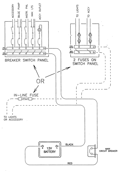
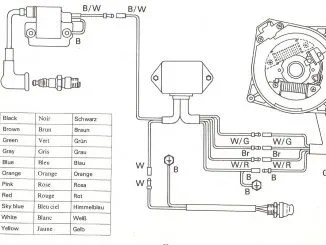
Outboard motor wiring diagrams can be a confusing and intimidating task for most boat owners. Fortunately, these diagrams are relatively simple to read and understand. Outboard wiring diagrams typically include the following components: a starter switch, a battery, an ignition switch, a power pack, and a kill switch. The diagram will also identify the wires that go to each component, as well as the colors of the wires.
It is important to understand the basic functions of each component in order to correctly wire the outboard motor. The starter switch is the main power source for the motor, and it should be wired directly to the battery. The ignition switch sends power to the motor when the key is turned on and then turns off the motor when the key is turned off. The power pack is responsible for providing the right amount of electricity to the motor, and it should be wired to the battery and the starter switch. The kill switch is a safety feature and should be wired between the ignition switch and the power pack.
The outboard motor wiring diagram also includes information about the different types of connectors and terminals used. These connectors are used to connect the various components together. It is important to use the correct connectors in order to ensure a proper and safe connection. Additionally, the diagram should indicate the type of wire that is used to make the connections. This type of information is important to ensure that all of the components are properly wired and that all safety precautions are taken.
Outboard motor wiring diagrams can be an invaluable tool for anyone looking to install, repair, or maintain their outboard motor. By understanding the basics of the diagram, one can easily troubleshoot any issues that may arise. Additionally, these diagrams can help to make sure that the motor is wired correctly so that it can run at its peak performance.

Wiring Diagrams Honda Outboard Motor Bf135a User Manual Page 114 118 Original Mode

Mercury Outboard Wiring Diagrams Mastertech Marine

Mercury Outboard 50hp Oem Parts Diagram For Starter Motor Solenoid Rectifier And Wiring Harness Boats Net

Wiring Diagram 300ap The Hull Truth Boating And Fishing Forum

Mercury Outboard Wiring Diagrams Mastertech Marine
2x New Cdi Switch Box 90115150200 Mercury Outboard Motor 332 7778a12 Switchbox Online In Taiwan B074m1x7qn
Wiring Twins W 3 Batteries Help Reviewing Diagram The Hull Truth Boating And Fishing Forum

Diagram For Main Wire Harness Honda Marine Bf90dk0 Lhta 90 Hp Outboard Motor
Viewing A Thread 2 Wire Motor Trim Wiring Diagram

Electrical System Wiring Diagram 1998 Crowley Marine

Wiring Diagram For Older Boat Continuouswave

Free Outboard Wiring Diagrams Manuals Net

Mercury Outboard Wiring Diagrams Mastertech Marine

Wiring Trolling Motors Correctly Safely Pumpupboats Com

Wiring Diagram Motor Boats Outboard Mount Pleasant Png 1416x759px Boat Deck Electronics
Wiring Up Yamaha 30 Boat Design Net
Clymer Wiring Diagrams Outboard Motors And Inboardoutdrives 1956 1989 Bwd1 Online In Senegal 53761063

Have A 1972 Evinrude 65 Hp Engine That Quits After About 5 Min On The Water With No Spark New Plugs Burns Really
