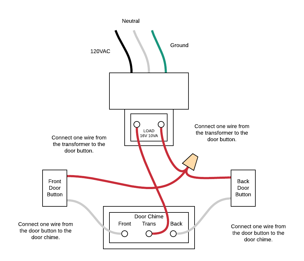
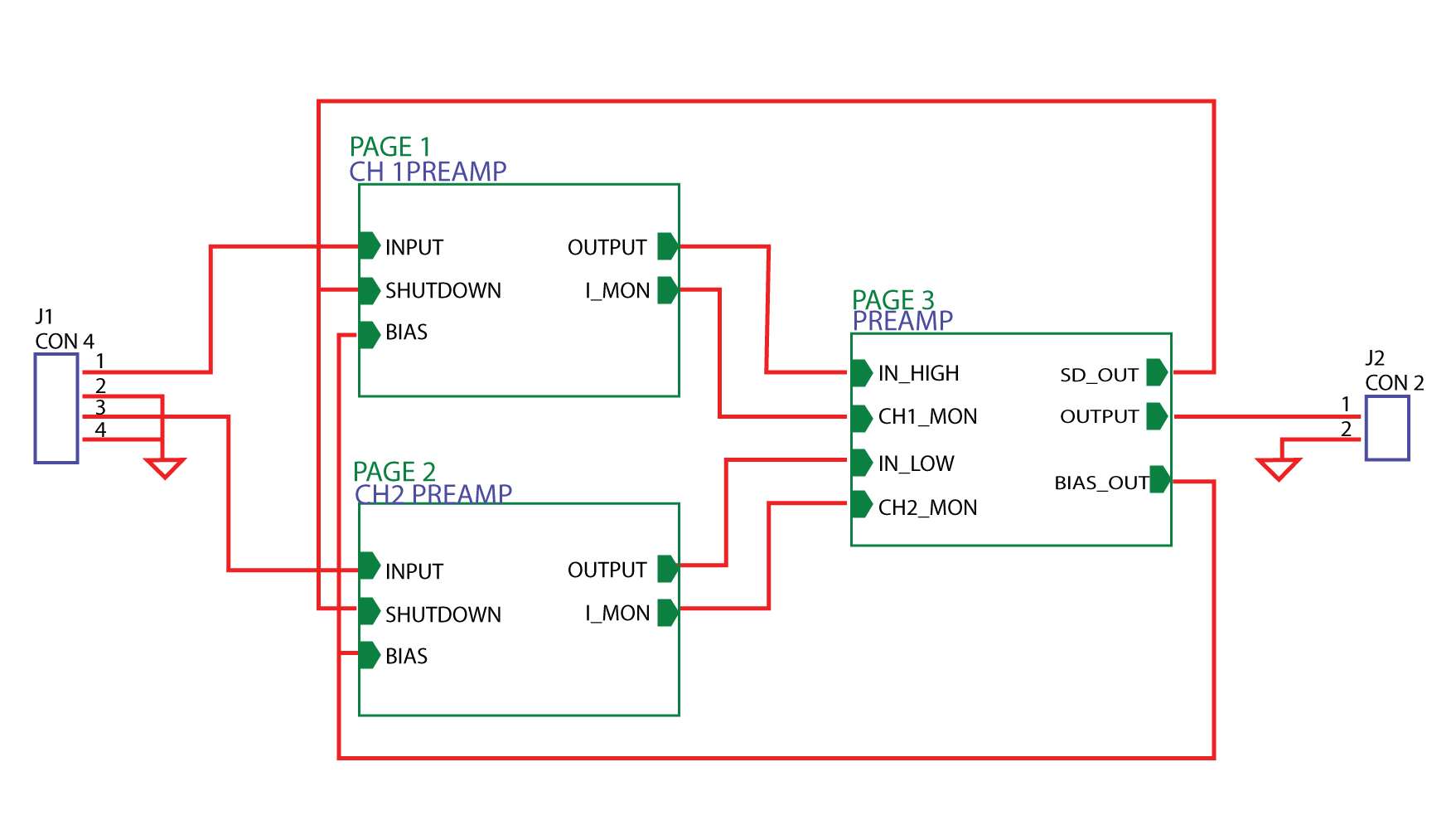
Schematic drawing, also known as a wiring diagram, is an essential tool used in the design and construction of electrical systems. It is a detailed visual representation of how the system works and how each component is connected. Schematic drawings are used to communicate both the physical layout and the electrical connections of a system.
Schematic drawings are typically used by engineers, electricians, and other professionals who need to understand the complex workings of an electrical system. They are used to identify the electrical components in a system and the connections between them. These drawings are also used to troubleshoot and diagnose problems. By examining the schematic drawing, professionals can quickly pinpoint and identify the source of any issues.
The schematic drawing is a valuable tool for any professional who needs to understand the complexities of an electrical system. It provides a clear visualization of the system, so that it can easily be understood and worked on. It is also a powerful tool for troubleshooting and diagnosing any issues. By understanding the power of schematic drawings, professionals can quickly and accurately identify and address any problems with an electrical system.

How To Read A Schematic Learn Sparkfun Com

A Simple Schematic Drawing Tutorial For Eagle Build Electronic Circuits

Drafting For Electronics Schematic Diagrams

Electronics Schematics Commonly Symbols And Labels Dummies

Learn To Read And Understand Single Line Diagrams Wiring Eep

How To Draw A Schematic Diagram Inst Tools

Difference Between Pictorial And Schematic Diagrams Lucidchart Blog

Learn To Successfully Analyze Single Line Schematic P Id Logic And Wiring Diagrams Eep

Schematic Diagram Maker Free Online App

Schematic Diagram Of A Basic Single Phase Ups Scientific
:max_bytes(150000):strip_icc()/Yuri_Arcurssubwaymap-5c4df0fd46e0fb0001f21f5e.jpg?strip=all)
What Is A Schematic Diagram

How To Draw And Design A Pcb Schematic Sierra Circuits

What Is Block Diagram Everything You Need To Know Edrawmax Online
:max_bytes(150000):strip_icc()/kr7ysztofwiringdiagram-5c4df148c9e77c0001f32271.jpg?strip=all)
What Is A Schematic Diagram

How To Read A Schematic Learn Sparkfun Com

Circuit Diagram And Its Components Explanation With Symbols

Drafting For Electronics Schematic Diagrams

Learn How To Analyze Mv Switchgear Wiring Diagrams And Single Line Diagram Eep

Drafting For Electronics Schematic Diagrams
