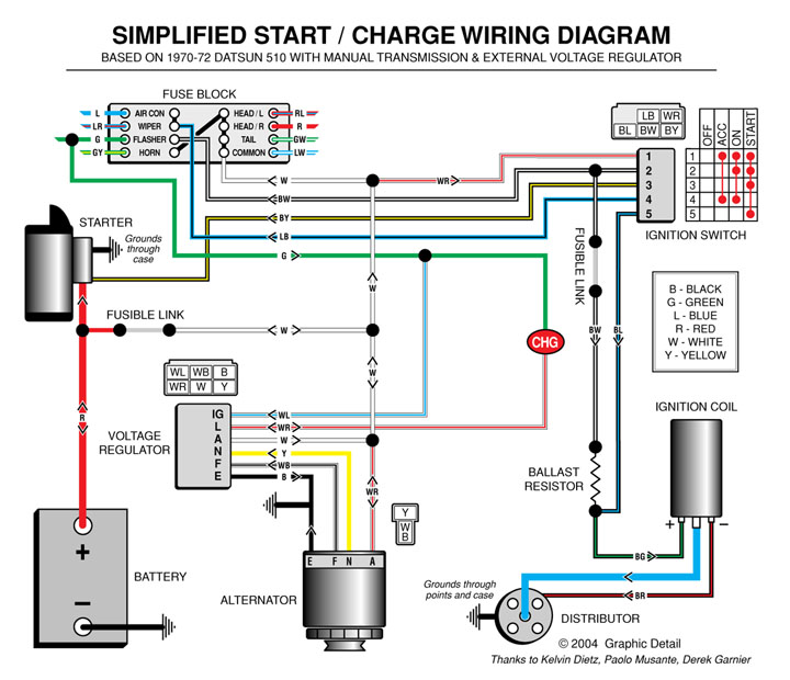
Wiring Diagram of Alternator and Voltage Regulator: A Guide to Electrical Safety
When it comes to electrical safety, wiring diagrams are essential. They help ensure that all components are properly connected, and that no dangerous voltages or currents are present. When it comes to the alternator and voltage regulator, a wiring diagram is especially important. This guide will explain how to read and understand wiring diagrams for alternator and voltage regulators.
The first step in understanding wiring diagrams for alternator and voltage regulators is to recognize the symbols used. These symbols represent components in the system, such as resistors, capacitors, transistors, and switches. It’s also important to familiarize yourself with the different types of connections that can be made. These include series and parallel connections. With a basic understanding of the symbols and connections, you should be able to interpret the wiring diagrams for the alternator and voltage regulator.
Next, you’ll need to pay attention to the colors used in the wiring diagrams. Different colors indicate different voltages and currents. For example, red usually indicates a hot wire, while blue denotes a neutral wire. Paying attention to the colors is essential in order to prevent any shocks or fires.
Finally, it’s important to take safety precautions when dealing with electrical wiring. Make sure to wear protective gloves and safety glasses, and never touch any exposed wires. If you’re unsure about any aspect of the wiring, consult a professional electrician.
Reading and understanding wiring diagrams for alternator and voltage regulators is an essential part of electrical safety. With a basic understanding of the symbols and colors used, and a few safety tips, you’ll be able to read and interpret these diagrams with ease. Knowing how to read and understand these diagrams can help you keep your home and business safe from potential hazards.
As Is Charging System Wiring Diagram For 1969 Mustang With Tachometer No Ammeter Vintage Forums

Self Build Adjule Alternator Controler

Par 4 9 6

Tech Wiki Ir Alternator Conversion Wiring Datsun 1200 Club

Joergs Motorcycle Pages Voltage Regulator
Voltage Regulator

Wiring Diagram Engine Regulator Full For Android

Vw Generator Alternator Wiring Guide
Voltage Regulator Int How It Works Ih8mud Forum

Thesamba Com Bay Window Bus View Topic Unknown Bosch Component Voltage Regulator Dual Battery Relay

Ka Alternator And Voltage Regulator The 510 Realm

Alternator Regulator Troubleshooting
Voltage Regulator

1971 Datsun 1200 B110 Alternator Conversion Forum Main Club

Aircraft Wiring

Fuel Injection Technical Library Alternator Files
Voltage Regulator Wire Cut Need Advice Opel Gt Forum
1970 C10 Battery Alternator External Regulator Issue The 1947 Present Chevrolet Gmc Truck Message Board Network


