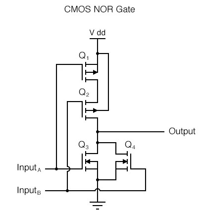
Circuit Diagram Of 3 Input Cmos Nor Gate
A circuit diagram of a 3-input CMOS NOR gate is a visual representation of an electrical circuit. It uses standardized symbols to identify the components of the circuit and shows how they are connected. This type of diagram is used in electronics to help troubleshoot and diagnose problems with circuits.
The 3-input CMOS NOR gate is a basic logic gate, which can be used to create a variety of logic functions. It is made up of two MOSFETs, one p-type and one n-type. The p-type MOSFET acts as an input and the n-type MOSFET acts as an output. When power is applied to the input, the output will be the inverse of the input.
The circuit diagram for a 3-input CMOS NOR gate is simple, but it is important to understand the components that make up the circuit. The main components of the circuit are the MOSFETs, the resistor, and the capacitor. The MOSFETs are the essential part of the circuit, while the resistor and capacitor serve to control the current flow through the circuit.
Understanding the circuit diagram of a 3-input CMOS NOR gate is important for anyone involved in the design, construction, or repair of electronic circuits. It is also useful to have a working knowledge of the components and how they interact with each other in order to troubleshoot and diagnose any issues with the circuit. With this knowledge, engineers can quickly identify the root cause of any problems with their circuits.

Cmos Nor Gate Details Hackaday Io
How Many Transistors Are In A 3 Input And Gate Quora

Introduction To Nor Gate Projectiot123 Technology Information Website Worldwide

Cmos Vlsi Design Introduction Ppt Online

Nand And Nor Gate Using Cmos Technology Vlsifacts
How To Draw Nand And Nor Gates Using Cmos Logic Quora
Lab6 Designing Nand Nor And Xor Gates For Use To Design Full Adders
What Is The Output Of A 4 Input Nand Gate When Only 3 Or 2 Inputs Are Applied Quora

Cmos Nand Gate Circuit Diagram Working Principle Truth Table

Understanding Digital Buffer Gate And Logic Ic Circuits Part 4 Nuts Volts Magazine

E77 Lab 3 Laying Out Simple Circuits

Layout Of Logic Gates Digital Cmos Design Electronics Tutorial

Layout Of The Nor 3 Gate Umc 0 18 μ M Scientific Diagram

Chapter 10 Digital Cmos Logic Circuits 1

Cmos Gate Circuitry Logic Gates Electronics Textbook

And Or Gate Using Cmos Technology Vlsifacts

Combinational Mos Logic Circuits
