The DC motor control circuit diagram for Ford reverse is a vital tool for anyone working with electric motors. By providing an accurate and detailed schematic of the motor's electrical system, this diagram can help users understand how their motor works and how to troubleshoot it if something goes wrong. This article will provide an overview of the basic components of the DC motor control circuit diagram for Ford reverse, as well as some tips on how to use it.
At the heart of the DC motor control circuit diagram for Ford reverse is the motor itself. This motor consists of two main parts: the stator and rotor. The stator contains coils which are arranged in a circular pattern and the rotor contains magnets that align with the stator's coils. As current is applied to the motor, it creates a magnetic field which turns the rotor and causes the motor to spin.
The DC motor control circuit diagram for Ford reverse also includes several other components that work together to ensure that the motor runs correctly. These components include a voltage regulator, rectifier, and a capacitor. The voltage regulator helps to regulate the voltage that is applied to the motor, while the rectifier converts the alternating current from the battery into direct current for the motor. The capacitor helps to store energy for the motor when it is not running, providing a steady supply of power to the motor.
Finally, the DC motor control circuit diagram for Ford reverse includes a variety of switches and indicators that allow the user to control the speed of the motor. By adjusting these switches, users can increase or decrease the speed of the motor, depending on the requirements of the application. Furthermore, the indicator lights on the diagram can help users identify any problems with the motor, such as overheating or overloading.
Understanding the DC motor control circuit diagram for Ford reverse is essential for anyone working with electric motors. By learning about the components of the diagram and how they work together, users can ensure that their motor runs correctly and safely. With the right knowledge, users can confidently troubleshoot any problems they may have with their motor.

500w 24v Dc Electric Motor W Reverse Control Box Low Noise Durable Brush Com

Forward Reverse Dc Motor Control Diagram With Timer Ic

Ford Knew Focus Fiesta Had Flawed Transmission Sold Them Anyway

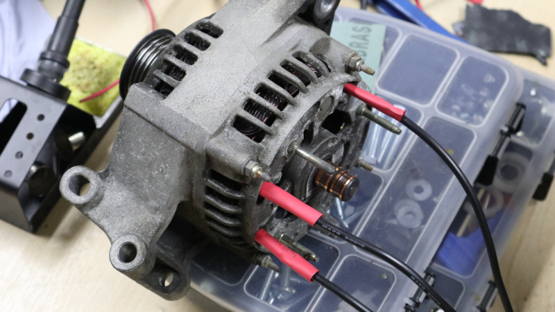
Car Alternators Make Great Electric Motors Here S How Hackaday

Robot Room H Bridge Dc Motor Schematic
The Circuit Diagram For Dc Motor Forward And Reverse Direction Scientific

Lab Dc Motor Control Using An H Bridge Itp Physical Computing

Sd Controllers

Motor Forward And Reverse Direction Control Using Limit Switches

Results Page 30 About Infra Red Motor Searching Circuits At Next Gr

The Circuit Diagram For Dc Motor Forward And Reverse Direction Scientific

Sd Controllers

Results Page 18 About Pic Mcu Searching Circuits At Next Gr
Tesla Institute Electrical Engineering Electronics Automation School Dc Motor Control Forward Reverse With H Bridge Interlock Facebook

Operational Power Control Systems

Dc Motor Control Text Plcs Net Interactive Q A

Operational Power Control Systems
How Can We Switch A Single Phase Motor Forward Reverse And On Off With 6 Pin Quora

More Dc 51 Motor Sd Controller Reverse Engineering

